Quantcast
Channel: Microscope World Blog
Viewing all 422 articles
Browse latest View live

Mitutoyo Thickness Gages

$
0
0
There are quite a few Mitutoyo thickness gages available, each with different features. This post helps explain the different types of thickness gages and their intended uses.

Measuring Lens Thickness

Mitutoyo reverse anvil digital thickness gage 457-312S.
Digital Reverse Anvil Thickness Gage
The reverse anvil thickness gages are ideal for measuring lens thickness.  These thickness gages are available in dial or digital output. Measurements can be made in metric or inches.

The digital reverse anvil thickness gages have the ability to  transmit the data and save it to an excel file for further analysis.


Measuring Groove Thickness

Groove thickness blade anvil measuring gage.
Dial Groove Thickness Gage
The blade anvil thickness gages were designed for measuring groove thickness. The groove thickness gages have a knife-shaped anvil and plunger to enable contact with the bottom of grooves.

The blade anvil thickness gages are available in either metric or inches. Digital versions can switch back and forth between mm or inches. Optional data output devices are available to record measurements.


Measuring Tube Thickness

Mitutoyo tube thickness gage available in digital or dial.
Digital Tube Thickness Gage
The tube thickness gages have a ball anvil and point contact that make these thickness gages ideally suited for measuring the wall thickness of tubes.

The tube thickness gages are available with an inch dial measurement, mm dial measurement or a digital version that can switch between inches and mm. The digital tube thickness gage has optional data output devices that can be purchased to record and save measurement data.


Measuring Larger Object Thickness

Deep throat thickness measuring gage.
Deep Throat Thickness Gage
The deep throat thickness gages are ideal for making measurements that might not be right next to the edge of the sample.

Deep throat thickness are available in metric dial gages, inch dial gages and in digital deep throat thickness gages. The digital version can switch back and forth between inches and metric measurements. Additionally, data output devices can connect to the digital thickness gage for data output.


Measuring Paper, Film, Wire, Sheet Metal

Mitutoyo high accuarcy thickness gage for measuring paper, sheet metal and fine thin samples.
High Accuracy Thickness Gage
The high accuracy digital thickness gage was created for high precision measuring. With accuracy of +/-0.00015" and resolution to 0.001mm the high accuracy thickness gage is perfect for measuring thin samples such as paper, film, wire, sheet metal and similar thin materials.

This thickness gage is available in only a digital version and can switch between inches and mm with an LCD reading as well as data output for SPC analysis.


Basic Thickness Measurements

Flat anvil thickness gages available in dial or digital readout.
Flat Anvil Thickness Gage
The flat anvil thickness gages were created for a wide range of applications with various types of measuring faces.

These flat anvil thickness gages are available in a wide variety of models including dial inches with different accuracy ratings as well as dial metric models. The digital versions of the flat anvil thickness gages can switch back and forth between a metric and inch readout. Data output devices are available for saving and outputting data to a computer.


Leaf Thickness Gages

Mitutoyo leaf thickness gages.
Leaf Thickness Gage
The leaf thickness gages are available in either inches or metric. Each leaf is marked with its thickness and is detachable from the fan of leaves. The leaves are available with a straight or tapered blade.


If you have a specific thickness measuring problem that you are trying to solve, please contact Microscope World.

Human Lungs under the Microscope

$
0
0
The human lungs are a pair of spongy, air-filled organs that are located on either side of the chest (thorax). The windpipe (trachea) passes inhaled air to the lungs through its tubular branches called bronchi. The bronchi then develop into smaller and smaller branches (bronchioles), until they finally become microscopic.

Microscope image of human lung captured at 40x.
Human lung under the microscope at 40x magnification.


The bronchioles eventually end up in clusters of microscopic air sacs called alveoli. The alveoli are tiny sacs within the lungs that allow oxygen and carbon dioxide to move between the lungs and the bloodstream. Inside the alveoli, oxygen is absorbed into the bloodstream. Carbon dioxide, a waste product from metabolism, travels from the blood to the alveoili, where it can be exhaled. Between the alveoli there is a thin layer of cells called the interstitium, which contains blood vessels and cells that help support the alveoli.

Microscopy image of human lung captured at 100x.
Human lung under the microscope at 100x magnification.


The lungs are covered by a thin tissue layer called the pleura. This same kind of thin tissue covers the inside of the chest cavity, which is also known as pleura. A thin layer of fluid acts as a lubricant allowing the lungs to slip smoothly as they expand and contract with each breath.

Microscopy image of human lung at 400x magnification.
Human lung under the microscope at 400x magnification.

The images shown here of human lungs were captured using the RB30 biological lab microscope and a high definition microscopy camera. Images were captured to an SD card and downloaded to the computer.

Microscope image of human lung captured at 400x.
Human lung under the microscope at 40x magnification using a Plan Fluor Objective.

Learn more about the human lungs here. For microscopy related questions contact Microscope World.

Digital Zoom Measuring Microscope

$
0
0
Microscope World offers the MWZ-DCM zoom digital measuring microscope system. This measuring microscope provides on-screen magnification of 34x - 220x. Digimatic indicators provide precise measuring capability. The USB camera offers 3 megapixels and includes software for image capture and making measurements.

Microscope World digital zoom measuring microscope.
Digital Zoom Measuring Microscope System

Microscope stage with digimatic indicators for making measurements.
Digimatic Indicators on Measuring Microscope Stage

Human Nonpigmented Skin under the Microscope

$
0
0
Pigmentation refers to coloring, and skin pigmentation disorders affect the color of the skin. Human skin gets its coloring from a pigment called melanin, which is produced by cells in the skin. When these melanin-producing cells become damaged or unhealthy, the production of melanin is affected as well. Some pigmentation disorders affect not only patches of skin, but also the entire body.

Microscope World image of human nonpigmented skin under the microscope at 40x.
Human nonpigmented skin under the microscope at 40x.

If the body produces too little melanin, the skin gets lighter. Vitiligo is a condition where the skin gets lighter in patches. Albinism is a genetic condition where the skin is affected by little or no melanin production. The skin might have no color (nonpigmented skin), or it may be lighter than the normal colored skin. It can also show up as patches of skin with no color.

Microscopy image of human nonpigmented skin at 100x.
Human nonpigmented skin under the microscope at 100x.


Another cause of nonpigmented skin can be a result of blisters or burns. These often result in skin becoming nonpigmented after it heals.

Microscope World image of human nonpigmented skin under the microscope at 400x.
Human nonpigmented skin under the microscope at 400x.


When the human body produces too much melanin, the skin becomes darker. Addison's disease, sun exposure and pregnancy can also cause the skin to become darker.

Human nonpigmented skin under the microscope at 400x using a Plan Fluor Objective Lens.

All images above were captured using the RB30 lab microscope. Images were captured to a SD card using the HDCAM4 HD microscopy camera.

Best Compact Stereo Zoom Dissecting Microscope

$
0
0
With a wide zoom range of 10x - 67x, the Richter Optica S6-BL15 provides a variety of magnifications for viewing rocks, insects, small parts or just about any other dissecting item. The stand has a compact footprint, designed specifically with schools in mind for placement in storage cabinets. With built-in reflected and transmitted LED illumination, there is plenty of light provided and dual rheostat controls allow for precise lighting control.

Best all around stereo zoom dissecting microscope.
Richter Optica S6-BL15 Stereo Zoom Microscope with 10x-67x

The Richter Optica S6-BL stereo microscope provides options for increasing / decreasing magnification including 10x, 15x and 20x eyepieces as well as a 0.5x and 1.5x auxiliary lens. View complete microscope magnification chart options here.

Stereo zoom dissection microscope most popular among US high schools.
The S6-BL is a popular high school dissecting microscope choice due to it's compact size.

Contact Microscope World with any questions regarding stereo zoom microscopes.

Rocky Mountain Spotted Fever under the Microscope

$
0
0
Rocky Mountain Spotted Fever is a bacterial infection caused by the bacterium Rickettsia rickettsii and transmitted by a tick. Without prompt medical treatment it can cause serious damage to internal organs such as the heart and kidneys.

Early signs and symptoms include high fever and severe headache. A few days later, a scratchy and red rash usually appears on the wrists and ankles and spreads in all directions from there. Some people do not develop a rash, which makes diagnosing the disease difficult. Other symptoms may include muscle aches, chills, nausea and vomiting, restlessness and insomnia. There are times when symptoms do not show up until two weeks after infection.

The infection usually responds well to prompt treatment with antibiotics. Rocky Mountain Spotted Fever was first identified in the Rocky Mountains, but can also be found in parts of Canada, Mexico, as well as South and Central America.

The images below of human skin infected with Rocky Mountain Spotted Fever were captured using the RB30 biological microscope along with a USB microscopy camera.

Microscopy image of Rocky Mountain Spotted fever at 40x magnification.
Skin infected with Rocky Mountain Spotted Fever under the microscope at 40x.

Microscopy image captured at 100x under a biological microscope of Rocky Mountain Spotted Fever.
Skin infected with Rocky Mountain Spotted Fever under the microscope at 100x.

Microscope World of infected skin under the microscope at 400x.
Skin infected with Rocky Mountain Spotted Fever under the microscope at 400x.

Microscopy image of skin infected with Rocky Mountain Spotted Fever captured at 400x magnification by Microscope World.
Skin infected with Rocky Mountain Spotted Fever under the microscope at 400x using a Plan Fluor Objective.

View more information about Rocky Mountain Spotted Fever at the Centers for Disease Control. Contact Microscope World for questions regarding microscopes and microscopy accessories.

Toothbrush Under the Microscope

$
0
0
Microscope World has a customer that manufactures toothbrushes and needed to view the bristles for quality control purposes. The images below were captured using the Huvitz Stereo Microscope along with a LED ring light  and a HD microscope camera.

Toothbrush microscopy image captured at 8x.
Toothbrush captured under the stereo microscope at 8x.

Microscope World image of a toothbrush captured at 10x magnification.
Toothbrush captured under the stereo microscope at 10x.

Microscope World image of a toothbrush under the microscope at 20x.
Toothbrush captured under the stereo microscope at 20x.

Microscopy image of a toothbrush at 25x.
Toothbrush captured under the stereo microscope at 25x.

Microscope World image of a toothbrush captured at 40x.
Toothbrush captured under the stereo microscope at 40x.

Microscope World image of a toothbrush captured under a stereo microscope at 50x.
Toothbrush captured under the stereo microscope at 50x.

For more information about microscopes contact Microscope World.

High Resolution Stereo Zoom HD Digital LCD Microscope

$
0
0
Microscope World is proud to introduce a new high resolution stereo zoom high definition (HD) digital microscope with LCD monitor. The FZ6-HD-LCD stereo microscope system was created specifically with quality control and industrial soldering work in mind. The high definition camera paired with the 1080p LCD monitor relieves eye strain caused by hours looking through the microscope at small parts or while soldering.

The high resolution stereo zoom microscope system has been designed with a large working distance of 177mm (7 inches) to allow room for working under the microscope. An extension post for the boom stand provides extra room for larger parts under the microscope.

A four-quadrant LED ring light as well as a polarizing filter eliminates glare when viewing metal parts. Zoom magnification of 5x - 67x allows for a wide range of magnification options.

The HD camera provides high definition quality resolution with a high speed frame rate of 60 frames per second at full resolution, eliminating jumpy movements under the microscope. Additionally, an SD card can be used to capture and save images quickly. The 13" monitor provides a large and clear image.

LCD tablet stereo zoom HD digital microscope boom stand system.
High Resolution Stereo Zoom HD Digital Microscope

For more information on stereo zoom HD microscope systems contact Microscope World.

Artery under the Microscope

$
0
0
Arteries are blood vessels that deliver oxygen-rich blood from the heart to the tissues of the body. Each artery is a muscular tube lined with smooth tissue that has three layers:
  1. The intima is the inner layer lined by a smooth tissue called endothelium.
  2. The media is a layer of muscle that lets arteries handle the high pressures from the heart.
  3. The adventitia is a connective tissue anchoring arteries to nearby tissue.
The largest artery in the human body is the aorta, the main high-pressure pipeline connected to the heart's left ventricle. The aorta branches into a network of smaller arteries that extend throughout the body. The arteries' smaller branches are referred to as arterioles and capillaries. The pulmonary arteries carry oxygen-poor blood from the heart to the lungs under low pressure, making these arteries unique.

The images below were captured using the Richter Optica U2D digital microscope with a 5 megapixel microscopy camera.

Richter Optica U2D with Infinity Corrected Optics and a 5mp digital USB microscopy camera.
U2D Digital 5mp Microscope

Microscopy image of artery, vein and nerve cross section under the microscope at 40x.
Microscopy image of artery, vein and nerve c.s. captured with U2D microscope at 40x.

Microscopy image of artery cross section under the microscope at 100x magnification.
Microscopy image of artery, vein and nerve c.s. captured with U2D microscope at 100x.

Microscope World image of artery, vein and nerve cross section captured under the microscope at 400x.
Microscopy image of artery, vein and nerve c.s. captured with U2D microscope at 400x.

Microscope World image of artery captured under the U2 microscope at 400x magnification.
Microscopy image of artery, vein and nerve c.s. captured with U2D microscope at 400x with a Plan Fluor objective.

Contact Microscope World with questions about microscopes or objectives.

Muskie Fish under the Microscope

$
0
0
The muskellunge (muskie) is a relatively uncommon freshwater fish native to North America. The muskellunge is the largest member of the pike family, Esocidae. Muskie fish are found in lakes and large rivers in the Great Lakes region of North America including Michigan, Wisconsin, Minnesota and into Canada.

Microscope World's customer, The Youth Conservation Alliance, is a 100 percent youth focused charity that teaches children about the environment, through the sport of Muskie fishing.

The image below was taken from a recent Muskie stocking venture between the Youth Conservation Alliance and the Department of Natural Resources in Wisconsin. The Muskie fish were stocked in Round Lake in northern Wisconsin.

Muskie fish being restocked in Round Lake Wisconsin.
Muskie Fish in Round Lake, Wisconsin
Muskie fish scales are similar to that of a tree and the fish can be aged by counting the larger rings. The image below of a muskie fish was captured under the Motic BA310 biological microscope at 600x using a microscopy camera. This fish is estimated to be six or seven years old.

Muski fish scale captured under a biological microscope at 600x magnification.
Muskie fish scale captured at 600x under a biological lab microscope.
Below are the fish gills of a healthy muskie fish captured at 1000x magnification.

Healthy muskie fish scales under the microscope at 1000x magnification.
Healthy muskie fish gills under the microscope at 1000x.
Below are the fish gills of an unhealthy fish that was near death, also captured at 1000x magnification. Notice the blood clotting in the gills. The sickness of this particular muskie fish was unknown.

Unhealthy muskie fish gill showing blood clotting under the microscope at 1000x.
Unhealthy muskie fish gills with blood clotting under the microscope at 1000x.
Below is a photo of a parasite that had embedded itself into the soft tissue of the fish gill where it was eating away at the blood cells.

Microscopy image of a parasite under a fish gill.
Parasite embedded into the soft tissue of the fish gill under the microscope.
All images courtesy of the Youth Conservation Alliance were captured during youth muskie research projects onsite at the State Fish Hatcheries while the children were participating.

Cheek Cells under Phase Contrast Microscope

$
0
0
Phase contrast microscopes are used to examine specimens that are the same color as their background and need a bit of "pop" in order to differentiate them. Samples where staining is not an option (or might kill the specimen) often utilize phase contrast.

Phase contrast microscopy image of cheek cells captured at 100x under a phase contrast microscope.
Cheek cells captured at 100x under a phase contrast microscope.

In the image above you may notice a few blue highlights around several of the cheek cells. These are actually air bubbles that were caught between the microscope slide and the cover slip when the sample was prepared.

Huvitz HRM-300 3D Profiler Microscope System

$
0
0
The world of microscopy is a fascinating place and using digital technologies such as 3D profiling, are allowing us to analyze samples in ways that were extremely difficult and sometimes not possible in the past.

I decided to get familiar with the Huvitz HRM300 series metallurgical microscope and its Panasis 3D profiling system software to see what could be done with this technology and how user friendly it is. I used the LUSIS HC-20CU microscopy camera that is included with this package to capture images and video of a circuit board.

Microscope 3D Image profiling system HRM300 from Microscope World
Huvitz HRM300 3D Profiler System with Camera, Control Box and 3D Imaging Software

Microscope mechanical stage with circuit board.
Circuit Board on 100mm x 100mm Travel Mechanical Stage

Huvitz 3D profiler Panasis software and control pad.
Panasis Interface on left monitor, User's Manual on right and Control Pad
HASP Key & USB to RS232 Adapter

There were some basic configurations and a calibration that I needed to perform, but afterward, and with a little help from the manual's step-by-step instructions, I was ready to take an Extended Depth of Focus photo of the circuit board.


Panasis extended depth of focus software microscopy circuit board image.
Panasis Extended Depth of Focus Image of the Circuit Board

Using the mechanical stage and viewing the live image on the monitor was simple enough and soon I found the area that I wanted to view. Under the 3D Profiler tab I set the top and bottom image reference points for the image and on the Extended Depth of Focus (EDF) tab I selected Auto and then entered the height intervals to be taken between image stacks. I then clicked Start and sat back while the profiler did its work.

The Huvitz HRM-300 microscope's stage began to move between the top and bottom limits of the z-axis with a quiet motorized sound. A few seconds later a very detailed and crisp image of the circuit board appeared on the screen. I was impressed by the clarity of the image, but now it was time to see it in 3D. So I clicked on the 3D icon that appeared in the top right corner of the image and . . . 

Microscopy 3D image of circuit board captured under HRM300 Huvitz metallurgical microscope with 3D profiling.
3D Image of Circuit Board under the Microscope!
The Panasis software allows for all types of measurements to be conducted so that the data and statistics needed are a few simple selections away.

Microscope 3D image of circuit board with image texture blending to see sample's surface at designated ratios.
Image Texture Blending to help see sample's surface at designated ratios.

Making profile measurements with the Huvitz HRM-300 metallurgical microscope with 3D profiling.
Making Profile Measurements

Huvitz HRM-300 3D Image profiler software showing volume measurements of a circuit board.
Volume / Area Measurements

Surface analysis microscope with 3D imaging software.
Step Measurements & Lighting Enabled with Histogram for Convenient Surface Analysis.

The overall user interface was pretty straight forward and the manual and other support options for the Huvitz HRM-300 series microscope, Panasis 3D profiling imaging software, and the camera made for a productive and user-friendly experience.

There are a lot of other cool features that come along with this microscope 3D profiling system including the following:
  • The ability to obtain wide panorama imaging of your sample, which greatly extends the microscope's field of view.
  • Automatic optimized contestant lighting when observation magnifications are changed.
  • Environment friendly functions that are good for both your microscope, the sample and the environment. The ECO setting goes into auto-power saving mode when you walk away from the system. Bulbs last longer and energy is saved. You can adjust the sleep mode time through the software.
  • Additional options are available including a variety of objectives, a motorized nosepiece, motorized stage and reflected and transmitted illumination.
 Do you have experience using the Huvitz HRM-300 3D Profiler Microscope? How has it worked for you and what are your thoughts on the 3D digital microscopy technology? Microscope World would love to hear from you regarding with questions or comments on this microscope system. Contact Microscope World and ask specifically for microscopy specialist Sean Page. Stay tuned for more of Sean's adventures in microscopy at Microscope World.

Ovary under the Microscope

$
0
0
The ovary is one of two reproductive glands in women. The ovaries are located in the pelvis, one on each side of the uterus. Each ovary is about the size and shape of an almond. The ovaries produce eggs (ova) and female hormones. During each monthly cycle, an egg is released from one ovary. The egg travels from the ovary through a fallopian tube to the uterus. The ovaries are the main source of female hormones, which control the development of female body characteristics, such as the breasts, body shape and body hair. They also regulate the menstrual cycle and pregnancy.

The images below of an ovary were captured with the RB30 lab microscope using the DCM3 3.2 megapixel microscope camera and software. The first three images were captured using Plan Achromat objective lenses, and the final image was captured using a Plan Semi Apochromat Fluor 40x objective lens.

Microscopy image of an ovary at 40x magnification.
Ovary captured under a lab microscope at 40x magnification.

Image of an Ovary under a lab microscope at 100x magnification.
Ovary captured under a lab microscope at 100x magnification.

Microscope image of an ovary captured by Microscope World.
Ovary captured under a lab microscope at 400x magnification.

Microscopy image of ovary under the microscope at 400x magnification, captured by Microscope World.
Ovary captured under a lab microscope at 400x magnification using a Plan Semi Apochromat Objective.


Contact Microscope World for further information on microscopy solutions.

Wildberry and a Guest Insect

8 Tips to Capture Great Microscopy Images Before the Fluorescence Fades

$
0
0
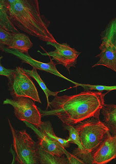
Fluorescence microscope image.Fluorescence is a great technique for microscopy. It provides amazing contrast and allows us to selectively view the objects that interest us without being obscured by surrounding structures. The one big drawback it has over brightfield microscopy techniques is bleaching. Even the brightest fluorescently labeled samples will eventually fade. However, there are several things you can do to prolong the effective fluorescence and capture some great images before they fade into oblivion.

  1. Use DIC or Phase Contrast to find your sample.
    After you place your sample on the stage, don't switch to fluorescence immediately. Use brightfield illumination such as phase contrast or DIC to find a suitable area to image. Once you find the right spot you can take a quick peek with fluorescence to make sure the fluorescent label is visible.
  2. Power down.
    Unless you are using very dim fluorophores, you most likely will not need the full power of your UV light source. Most LED based light sources allow you to adjust the light intensity. Start with the lowest intensity and gradually increase it until you can just see the structure you want to image (it doesn't have to be that bright - remember that your microscopy camera will pick up a lot more light than your eyes do). On confocal or other laser-based systems a laser power of just a few percent is often sufficient for a well-labeled sample. If you are using a mercury or xenon lamp, consider using an attenuator to limit the amount of light reaching the sample.
  3. Tune your camera settings.
    Dedicated microscope cameras have been optimized for fluorescence imaging and have many features that will allow you to collect data as quickly as possible before your sample fades. Avoid color cameras as the Bayer mask in front of the chip absorbs a significant amount of light. Check your camera's operating manual for settings such as gain, binning modes, sub-frame readout, and dynamic range. All of these can be adjusted to increase image capture speed but there is usually some cost in terms of noise or resolution. Some camera control interfaces allow you to use high-speed features in a preview mode (for example, while you’re focusing the sample) and then automatically switch to a high quality mode to capture the image. It is a good idea to test camera settings on a positive control or spare sample before imaging your critical experiment.
  4. Use objectives with high numerical aperture values.
    The higher the numerical aperture of the objective, the more light will be collected from the sample which, in turn, allows you to reduce the exposure time. Find the objective with the highest numerical aperture that will still give you the field of view that you need. If available, use oil immersion objectives as they typically have a higher NA than comparable dry lenses.
  5. Avoid z-stacks or autofocus.
    If you have a motorized Z-drive on your system, you may be tempted to use some of the enhanced functions that this feature offers such as autofocus and Z-stack imaging. While these may be necessary if you are doing timelapse imaging or you have thick specimens, keep in mind that you are prolonging the exposure of your sample to fluorescent light when you use these features.
  6. Use bright, stable fluorophores.
    There is considerable variability in the brightness and stability of many of the fluorophores typically used in fluorescence microscopy. Before you grab the first fluorescent dye you can find in your freezer, take a moment to look up the quantum yield (brightness) and photostability of the dye. These may not always be easy to find but picking the right fluorophores can save you a lot of trouble later on.
  7. Use an anti-fading agent.
    Using an anti-fading agent in your mounting medium can dramatically decrease the speed of bleaching in your sample. There are some home brew recipes available but commercial products such as ProLong and VECTASHIELD are not too expensive and work extremely well.
  8. Use dedicated, high-efficiency filter sets.
    Many fluorescence microscopes come with a standard filter set for imaging red, green, and blue fluorescence. These work well enough for routine imaging with a variety of common fluorophores such as DAPI, FITC, TRITC, Texas Red and even GFP. That versatility comes at a cost, though, as these filter sets usually don’t have the highest transmissions and the broad band pass values can cause bleed-through when imaging dyes that are spectrally close. If you know you will be doing a fair amount of imaging with a particular fluorophore, it is probably worthwhile investing in a dedicated, high-efficiency, filter cube for that dye.

If you have questions regarding fluorescence microscopy please contact Microscope World.

Apple under the Microscope

$
0
0
The apple is the fruit from the apple tree, a deciduous tree in the rose family. The apple tree originated in the Middle East about 4,000 years ago, and is one of the oldest known fruits.

As with the old adage, "An Apple a Day Keeps the Doctor Away" the apple is a powerhouse of nutrients with a great source of fiber, vitamin C, heart-healthy potassium, B-complex vitamins, phytonutrients, antioxidants, and many more health and medicinal benefits.

The vitamins present in apples are the key in maintaining red blood cells and keeping the nervous system in good health. The nutrients in apples are unduly present in the skin of the apple, which is the most valuable part of the fruit with respect to its nutrient substance.

The images below are of a cross section of an apple on a prepared slide under the UX-1D plan achromat digital microscope.

Microscopy image of an apple under the microscope at 40x.
Apple under the UX-1D digital microscope at 40x

Microscpy image of an apple at 100x.
Apple under the UX-1D digital microscope at 100x

Micorsocpy image of an apple at 400x by Microscope World.
Apple under the UX-1D digital microscope at 400x

For more information on digital microscopes contact Microscope World.

Understanding Stereo Microscope Optics

$
0
0
There are two types of optical designs for stereo microscopes.
Each stereo microscope system has its advantages. Specifically, with the CMO system (a), because of the optical design, there is a capacity for much higher magnification and resolution. This design is most commonly used in research applications requiring both higher magnification and higher resolution (NA). This design results in a relatively flat field and does not generate a pronounced three dimensional image.

For the Greenough system, the primary advantage is that it provides a pronounced three dimensional image and is very useful for relatively low magnification and inspection of items with "depth". Because of the "V" design of the optical path (b), as magnification is increased, both by the use of auxiliary lenses and higher magnification eyepieces, there is a divergence of the point on the subject where each optical path is focused and resolution appears to degrade. This is what limits the effective magnification range of this design to approximately 125x.

Stereo microscope CMO versus greenough optical design.
(a) CMO optical design (b) Greenough optical design

The images below were captured from the left and right eyetubes on a Greenough stereo microscope. As you can see, the crossline in the left image is offset to the left, and the crossline in the right image is offset to the right. Everything is exactly the same for these two images except for the moving camera from the left to the right eyetube. Specifically, this is exactly what a Greenough system should look like, because this is how the microscope system generates a three dimensional type of image.

Greenough stereo microscope versus CMO stereo microscope.
Greenough Stereo Microscope image from left eyetube and right eyetube.

If you have questions about which stereo microscope system will best meet your needs please contact Microscope World.

Stomach Fundic Region under the Microscope

$
0
0
The fundic region of the stomach is formed by the upper curvature region of the organ. The glands in this region are known as gastric or fundic glands and extend all the way to the muscularis mucosae. From three to seven glands open into the base of each gastric pit. Each gland has a fairly long, narrow neck and a short, wider base. At their base, the glands may divide into two or three branches which become slightly coiled. In the fundic region, almost the entire lamina propria (mucous membranes) are occupied by glands. The lamina of the glands are usually not identifiable and they usually appear more like cords of cells. The only "typical" lamina propria can be seen in the areas between the foveolae and around the bases of the glands.

The cross sections of the fundic region of the stomach shown below were captured using the RB30 lab microscope and a HD high definition microscopy camera.

Microscopy image of fundic stomach region.
Stomach Fundic Region c.s. under the RB30 microscope at 40x.

Microscope image of cross section of fundic region of stomach.
Stomach Fundic Region c.s. under the RB30 microscope at 100x.

Stomach lining under the microscope at 400x.
Stomach Fundic Region c.s. under the RB30 microscope at 400x.

Stomach lining microscopy image at 400x.
Stomach Fundic Region c.s. under the RB30 microscope at 400x using Plan Fluor Objective.

View more histology stomach images here.
For more information on microscopes and microscopy cameras visit Microscope World.

Dual Observer Stereo Teaching Microscope

$
0
0
The MWDVS Dual Head Teaching Microscope is a common main objective dual observer stereo microscope system with a custom mechanical stage that offers both coarse and fine focusing.

Dual Observer Stereo Microscope with Common Main Objective
Dual Head Teaching Stereo Microscope System

Some of the features of this unique microscope system include:
  • Option for five fixed magnifications or continuous zoom.
  • Common Main Objective stereo microscope
  • Custom mechanical stage with both coarse and fine focusing.
  • LED Dual pipe light illumination.
  • LED pointer so second observer can see what main observer is viewing
  • Solid metal heavy base
Common main objective stereo microscope system for teaching with dual observer heads.
MWDVS dual observer stereo microscope.

Common Main Objective Stereo microscope with dual observer heads for teaching.

Common main objective stereo microscope dual observer system with custom mechanical stage.
Mechanical Stage with ability to shine light up beneath stage, as well as coarse/fine focusing.

Cerebellum under the Microscope

$
0
0
The cerebellum, also known as the "little brain" is a structure located at the back of the brain, underlying the occipital and temporal lobes of the cerebral cortex. Although the cerebellum accounts for approximately 10 percent of the brain's volume, it contains over 50 percent of the total number of neurons in the brain.

Historically, the cerebellum has been considered a motor structure, because cerebellar damage leads to impairments in motor control and posture and because the majority of the cerebellum's outputs lead to parts of the motor system. Motor commands are not initiated in the cerebellum, rather the cerebellum modifies the motor commands of the descending pathways to make movements more adaptive and accurate.

The cerebellum is involved in the following functions:
  • Coordination of voluntary movements
  • Maintenance of balance
  • Motor learning
  • Maintenance of posture
  • Cognitive functions
The images below of the cerebellum were captured using the Fein Optic RB30 lab microscope with the HDCAM4 high definition microscopy camera.

Microscopy image of the cerebellum under the microscope at 40x.
Cerebellum c.s. under the microscope at 40x.

Cerebellum captured at 100x under the lab microscope.
Cerebellum c.s. under the microscope at 100x.

Microscopy image of the cerebellum captured at 400x by Microscope World.
Cerebellum c.s. under the microscope at 400x using plan fluor objective lens.

Contact Microscope World for more information on microscopes and microscopy cameras.
Viewing all 422 articles
Browse latest View live